4D Programming Cable
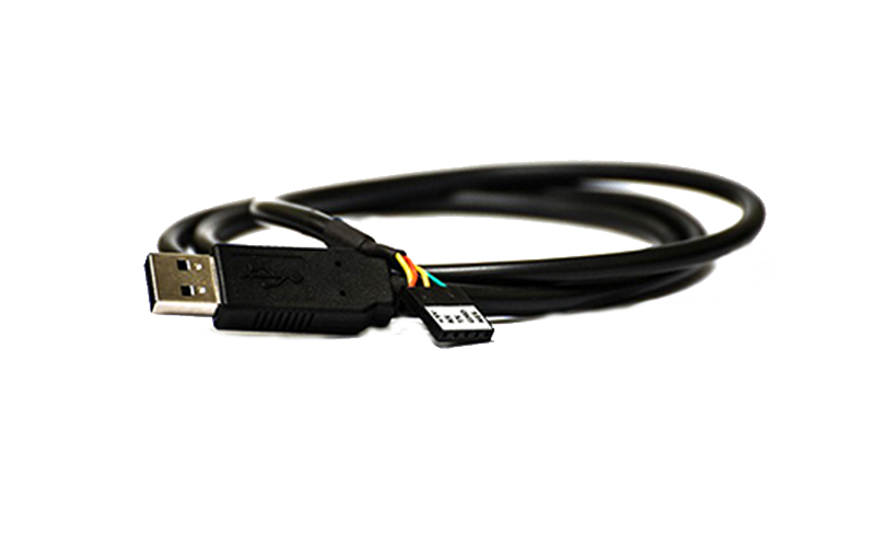
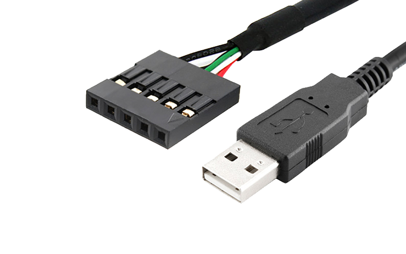
The 4D Programming Cable is a USB to Serial-TTL UART converter cable. It incorporates the Silabs CP2102 USB to Serial UART bridge IC (as used in the uUSB-MB5 module) which handles all the USB signalling and protocols. The cable provides a fast and simple way to connect all of the 4D devices that require TTL level serial interface to USB. The Programming Cable is also an essential hardware tool used for programming PmmC files and 4DGL user code downloads into the GOLDELOX and PICASO processors embedded in many 4D modules.
The cable contains a small internal electronic circuit board, utilising the CP2102 chip and special RESET circuitry, which is encapsulated into the USB connector at the end of the cable. The cable is RoHS compliant and is available with a 5pin female header (0.1″/2.54mm pitch) at TTL levels of 3.3V for RX and TX. The 5pin header is labeled with the appropriate signal names: +5V, RX, TX, GND, RESET which match the programming headers on the 4D devices. The cable also provides +5V DC supply to power up the target device. The cable is 1m in length and the circuitry is USB powered (USB 2.0 compliant full speed @ 12Mbps) and supports data rates from 300bps to 1Mbps.
Information about the cable
- USB 2.0 compliant Full Speed 12Mbps maximum speed.
- Hardware or Xon/Xoff handshaking supported; 300bps to 1Mbps.
- UART supports 5-8 bit data, 1-2 Stop bits, odd/even and no parity.
- Integrated EEPROM for Vendor ID, product ID, serial number, release number.
- Virtual COM port drivers allow operation with existing COM port PC applications.
- USB powered; -40 to +85 deg C temp range.
- Small size; circuitry built inside the USB connector.
- 1m in length
- RoHS compliant.
Typical Applications:
- The 4D Programming Cable makes an easy USB to Serial interface, so you can easily create:
- Interface micro-controller UART to USB
- USB to RS-232 converters
- USB to RS-422/RS-485 converters
- Upgrade legacy RS232 devices
- Make PDA and cellphone USB interface cables
- Serial Interface for barcode readers, POS terminals, etc.
The cable is designed specifically to interface directly with all 4D devices that use a 5pin programming header. In any non 4D device application, make sure the TX and RX lines from the cable are crossed over to the attached peripheral, that is, the TX from the cable connects to the RX of the target and the RX from the cable connects to the TX of the target device.
Driver Installation – Windows:
- Download the zip file from the link on the left, “Drivers for Windows”, into a folder on your system and unzip the file.
- Launch the application and follow the prompts given by the Install Wizard. This will copy all necessary files to a destination folder provided by the install wizard.
- You will be advised to read the terms of the “Licence Agreement”. If you accept then the installation will proceed. Click “Next”.
- Only change the “Destination Location” if there is a need to do so, otherwise accept the default location. Click “Next”.
- Now we are ready to install. Click the “Install” button to start the installation.
- When the “InstallShield Wizard Complete” window pops up you will need to select the tick box for the “Launch the CP210x VCP Driver Installer” option. Select this and click the “Finish” button.
- The next step will Install the Drivers, click the “Install” button. This will complete the final installation.
- You may need to restart your computer for the drivers to take effect. Do so if required.
- Attach the 4D Programming Cable to the USB port and you’re ready to use it.
How to determine which COM port is allocated to the 4D Programming Cable:
- There you will see the COM port that has been allocated for the Programming Cable.
- Take note of the COM port number (e.g. COM4) as you will need this when configuring the COM port for applications that need to communicate with the Programming Cable.
- Go to Control Panel and double click on the “System” Icon and the “System Properties” window will open up.
- Click on the “Hardware” window tab and then the “Device Manager” button.
- Go down the list and expand the “Ports (COM & LPT)” devices.
How to Increase available current from the USB port:
The link in the Software and Utilities section, on the left, “CP2102-Settings” contains a nice little utility program to increase the power (current) available from the Programming Cable. Default is 100ma which may not be enough for some devices. Up to 500ma is available on a USB port but the device (Programming Cable) must ask for what it needs from the host i.e. from the PC.
- Connect the 4D Programming Cable to the USB port.
- Unzip the file into a folder, name it anything you like.
- Run the application “CP210xSetIDs.exe”.
- A window will open up with lots small selectable boxes, we’re only interested in “Max Power (2 mA Units)”.
- There you’ll see a default value of 32 (this is in hex, dec=50). Each increment of this value will provide an extra 2ma of current from the PC to the Programming Cable. So if we want to draw 200ma we need to enter 64 and for 300ma we need to enter 96 and for 400ma enter C8 and so on.
- We can be greedy and go for the maximum so we need to change the value of 32 to FA. You can do so by highlighting this value with your mouse and typing FA. Maximum allowable current is 500ma for a USB device, so do not enter anything more than FA otherwise the setting will not take effect.
- Once the desired hex value is entered for the current we need, tick the small box next to it.
- Now click on the “Program Device” button (large button on the right hand side) and make sure the Programming Cable is attached to the USB port. This action will program the USB power descriptors within the CP2102 chip inside the cable with the power value that was entered.
- Now close the application.
- The above procedure only needs to be done once. So the next time the Programming Cable is attached to the USB port, it will receive the appropriate current from the USB port.