
How innovators are accelerating product development using commodity SBCs and display modules
The past ten years have seen a significant increase in the number of new consumer electronics-based products coming to market, and the pace shows no signs of slowing. You can find everything from an IoT-connected toothbrush to a petcam app that allows you to check up on your cat or dog when they are home alone.
Imagination is everything, and this seems to be driving the rate of new product innovations.
Look a bit deeper behind each design and you’ll probably find that it was developed using one or more of the techniques now available to all. We’re talking about the rise in 3D printing, putting 3D drafting and printing capabilities in the hands of the many. And it isn’t just the 3D printer that makes all this possible, it’s the availability of free online portals such as Tinkercad, where not only can you develop your own design, but you can then share it with others in the community, or perhaps use or modify a design that somebody else has produced. Add in an equally open and engaging community behind single-board computers (SBCs) such as the Raspberry Pi, Arduino and BeagleBone Black, and your great idea is almost in production!
So you have come up with your product design – perhaps you’ve made a couple of prototypes to show family and friends, but now you fancy having a go at ‘making it big’ by taking your product to market. Conducting market research and obtaining finance have always hampered those with good ideas, but now there is another route: crowdfunding. Crowdfunding sites such as Kickstarter and Indiegogo provide a forum to structure your product design ideas and gauge consumer interest, as well as a means of finance. If enough early adopters think your idea a good one, and the production plans are achievable and well thought-through, then you’ll quickly find you have the finance in place to get your business started.
There is another interesting aspect to the scenario above, which is that many of the inventors and innovators launching new products are not professionally trained engineers. Granted, an enquiring mind can pick up a lot of basic skills and knowledge by experimentation, but it is the passion and expertise innovators have for their new product that really provides the momentum to make an idea a reality. So many have come up with a product idea having been frustrated by the repetitive things they have to do, or tools they use in their daily lives, whether at home or work. Never has the phrase ‘Necessity is the mother of invention’ been more relevant.
When it comes to choosing an SBC there are tens of different boards available, many with a choice of configurations. Take the Linux-based Raspberry Pi, for example – introduced in 2013, and as of March 2018 there have been over 19 million Raspberry Pis sold. Now available in four different form-factor boards, the Raspberry Pi has been credited with kickstarting a resurgence in electronics as a hobby. The Raspberry Pi Zero W is one of the board variants, packing Wi-Fi, Bluetooth 4.1 and Bluetooth Low Energy wireless connectivity and a 1 GHz single-core ARM11 CPU and 512 MB RAM into a compact 65 x 30 x 5 mm footprint.

Figure 1 – Raspberry Pi Zero W (image courtesy of Raspberry Pi Foundation)
The Raspberry Pi board family has been widely adopted by non-engineer innovators and industrial automation manufacturers alike. Online communities and forums offer a vast range of programming tips and hardware interfacing techniques that help developers get their product working. It can be found at the heart of many low-volume industrial products, saving manufacturers the significant costs of developing a custom embedded system.
The Raspberry Pi has also spawned a whole industry that supplies a range of affordable add-on peripheral interface boards or ‘hats’, cases and display modules. A budding innovator is quickly able to assemble all the parts needed to prototype a new product idea. From the operating software perspective, the Raspberry Pi uses a popular Linux distribution that is extremely reliable and resilient in use, and well supported. Available programming languages include most popular high-level languages such as Python and C/C++ as well as more visual tools such as Node-RED and Scratch.
An example display suitable for use as the primary display across the whole Raspberry Pi family is the gen4-4DPi series from 4D Systems. Available in 4.3, 5 or 7 inch screen sizes with the option of resistive or capacitive touch controls, the 4DPi is designed to work with the standard Raspbian Operating System and takes its input from what would have been sent to the HDMI interface.

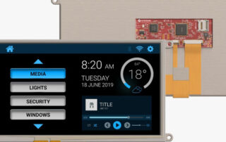
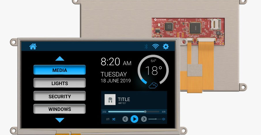
Figure 2 – gen4-4DPi-43T 4.3 inch display
The 4.3 inch 4DPi comprises a 480 x 272 pixel TFT screen (800 x 480 resolution for the 5 and 7 inch models) – see Figure 3 – and an adapter – see Figure 4. The 4.3 inch display has a typical frame rate of 20 frames per second, and is powered directly from the host SBC. No additional power supply is required, thus making the combination ideal for use in space-constrained products. Communication with the Raspberry Pi is achieved by a high-speed 48 MHz SPI connection that uses a compression technology to further improve data transfer speed. A Xilinx FPGA is used to process the SPI data and pass it to the LCD controller.

Assuming that you have a functioning Raspberry Pi Zero W, you simply follow the instructions provided in the gen-4DPi datasheet to connect the display to the SBC. This involves downloading and installing kernel updates from the 4D Systems website and changing a couple of boot options. It is also recommended that you calibrate the touch screen to ensure that it works correctly with your application and, if required, change the display orientation from landscape to portrait.
With a host of SBCs, modules and community support readily available, innovators have only their imagination to limit what can be designed.


")

